This post is also available in:
In fall 2004 my beefiest mount was a Losmandy GM8, which I still happily own. The most obvious upgrade would have been the G11, but back then, I simply could not afford it. The Synta EQ6 was a very cheap option, widely known for its very good price/performance ratio but also for its poor mechanical quality. I ran into a (like new) used one, which I paid about 750, or almost 1/4 of a new G11. In december 2004, I replaced its crappy original clock drive with a high-quality, belt-and-pulley GoTo system from Astromeccanica, called DA2.
I have since tried to fine tune my mount in a number of ways, but the road to full optimization proved to be really tough; I must admit I have really underestimated this task! The work is still in progress, and I hope sharing my experience will both provide the readers with some insight in the matter and (hopefully) enable the most experienced ones to help me shed some light on a number of issues.
All PE measurements mentioned in this article were made with a Philips webcam (either Vesta Pro or ToUcam Pro) with 5.6-micron pixels at 640 x 480 resolution at the prime focus of a SCT telescope. K3CCDTools was used for acquisition at a sampling rate of about 2.1 Hz (or a little more than 2 samples/sec). Finally, the PEAS program was used to process all raw data logs and frequency analysis. The EQ-6 worm period is about 480 seconds.
PLEASE NOTE: This article is NOT meant to give a detailed description of the assembling/disassembling process; many people have already done this job way better than I could do, so you just will find a selection of excellent online resources. Instead, I hereby want to share my hands-on experience.
12th December 2004: first PE measurement
As soon as I replaced the mount, I was curious as to its behavior as far as periodic error was concerned. Since I intend to use it also for prime-focus deep sky work, I wanted to make sure its PE was not too bad; it was also quite obvious that it could not be nsed for such application right out of the box. So, the first night out was on 12 december 2004, and here are my results:
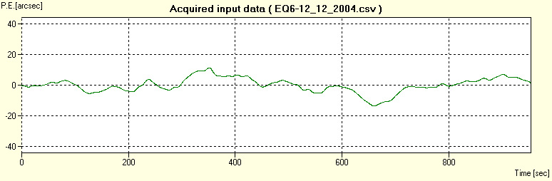
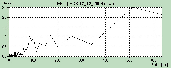
The first-light test (three worm periods) showed a quite irregular PE profile; however, the maximum peak-to-peak value was 25 arcsecs is not that bad for a mount which hadn’t undergone any modifications yet. Shortly after purhasing the mount, I was curious as to its behavior as far as periodic error was concerned. The FFT spectrum clearly shows the following main peaks:
| Period (s) | 86 | 93 | 127 | 173 | 257 | 343 | 515 |
| Worm period units | 0.18 | 0.19 | 0.26 | 0.36 | 0.53 | 0.71 | 1.07 |
| Intensity (arcsec) | 1.0 | 0.8 | 0.7 | 1.1 | 1.0 | 0.6 | 2.5 |
The above table also shows that :
- the highest component has a 515-s period, very close to the worm period.
- the total PE curve is spread over a broad frequency range (many components with significant intensity), thereby yielding its irregular shape.
This is probably an evidence of poor overall mechanical quality.
30th December 2004: second PE measurement
On 30th december 2004, I managed to re-test my mount, always with my good, old Celestron 8. This time the total data recording covered more than five worm periods, which even better. Below are the graphs from the raw data:
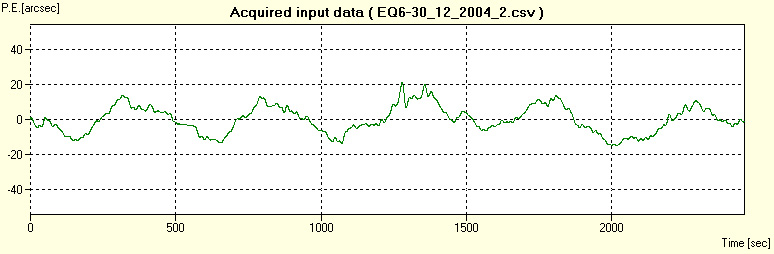
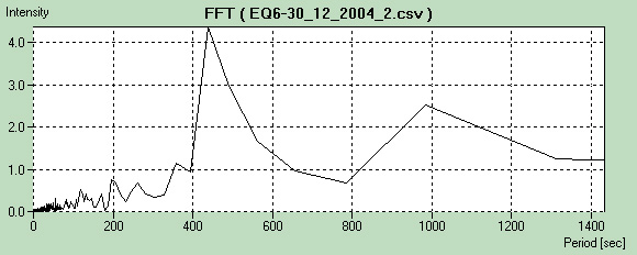
The periodic error is not exactly sinusoidal, with a total peak-to-peak maximum amplitude of 36 arcsecs. The main spikes in the frequency domain are arranged in the following table:
| Period (s) | 357 | 457 | 490 | 561 | 650 | 985 | 1310 |
| Worm period units | 0.74 | 0.91 | 1.02 | 1.17 | 1.35 | 2.05 | 2.73 |
| Intensity (arcsec) | 1.0 | 4.2 | 3.0 | 1.7 | 1.0 | 2.5 | 1.3 |
We highest spikes are hovering around a period of 440-490 seconds, which is most likely due to the worm rotation. Another component at 985 seconds might have something to do with the worm as well.
The conditions of the first two measurements were much alike: temperature from 1°C to 5 °C, almost no wind, total payload of about 9 kg + counterweights, etc. Yet, the results are significantly different: I really don’t have any reasonable explanation for this.
Preparing for the major overhaul
The above results clearly showed that EQ-6 was OK for visual observation or even webcam imaging, but not exactly suitable for long-exposure deep sky work with a simple digital SRL (which was my original aim), let alone a CCD camera.
By doing an extensive search on the Internet and registering with different on-line user groups, I got to know that many people had taken their mount apart and had significantly improved its performance just by regreasing it and fine tuning the gear mesh. Some had gone even one step further by lapping their worm and/or replacing the original bearings. Furthermore, I also found out that an Austrian guy (Mr. Richard Gierlinger) was making a high-precision worm and worm gear set. In early 2005, I got in touch with Mr. Gierlinger: at that time he didn’t have any set in stock, so I enrolled for next production run as soon as he got enough orders.
My gear finally arrived in mid-october 2005, but it was not early 2006 (Xmas vacations) that I a whole half day to spend on this endeavor. Just in case, I also bought a set of new bearings for both axes (RA and DEC).
Here comes D (= dismantling) – day 🙂
On 6 Jan. 2006, after carefully reading all the documentation over and over again, a friend and mine (who is an expert mechanic) and I took apart my EQ6. We dismantled both the DEC and RA assembly. Here is a summary of the work done:
- For both axes, we carefully removed the awful black yucky goo and replaced it with a good-quality white lithium-teflon grease (“Arexons GLT2” purchased from a good hardware store) rated at -25 °C to +120 °C.
- For the DEC axis, we changed the two small worm roller bearings (608-RS) and one of the three 6008-RS bearings. The EQ6 has three 6008’s for each axis: two of which hold the worm gear on the shaft, plus one lying alone, farther apart along the axis. We replaced the latter and not the other two.
- For the RA axis, we replaced the two 608’s as well. Please note we changed only the “lonely” 6008, and the 32208 tapered bearing, which by the way is the heaviest and beefiest bearing in the whole mount.
- For the RA axis, I also changed the worm/worm gear pair with Gierlinger’s precision set.
Important: many websites mention the alignment procedure of the worm/worm gear by measuring some lengths with a caliper, and subsequently making some spacer rings. However, I did not make this modification and used the original teflon rings. But I’ve come to thinking this step is very important. Any thoughts?
Replacement bearings were made by French-based SNR (608-RS and 32208) and SKF (6008-RS).
After putting everything back together, I fine-tuned the gear mesh of both axes until I got a very smooth feeling. It’s probably worth mentioning that at first the RA worm was not very even but had a clearly hard spot, which I managed to fix shortly thereafter. It may be worth noting that all these adjustments were made indoors at a temperature of about 20 °C.
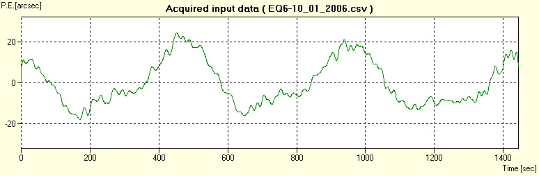
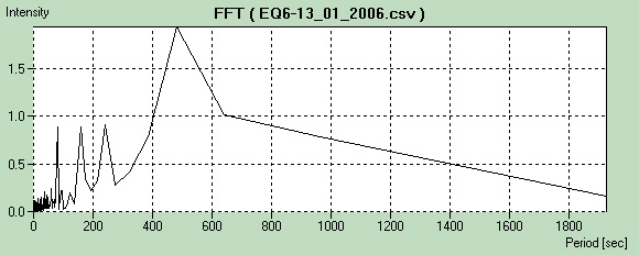
10th January 2006: third PE measurement
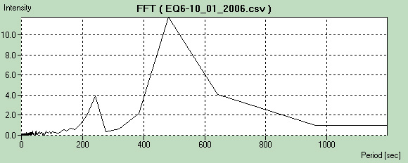
| Period (s) | 241 | 385 | 483 | 647 | 965 |
| Worm period units | 0.50 | 0.80 | 1.01 | 1.34 | 2.01 |
| Intensity (arcsec) | 4.0 | 2.1 | 11.5 | 4.0 | 1.0 |
Much to my despair, the results are very disappointing: the PE has actually worsened as compared to the first measurements. I can’t just believe my eyes! Furthermore, if we look at the frequency response graph, the sharpest spikes lie at 241, 483 seconds, which correspond almost exactly to 0.5x and 1.0 x worm rotation periods respectively.
Looks like I have to put the blame on the worm? Who knows… I’m really puzzled.
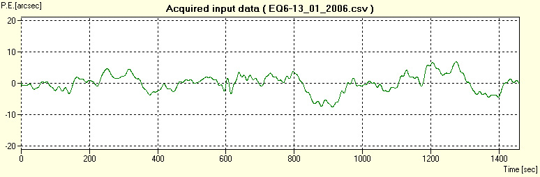
13 January 2006: fourth PE measurement
13 January 2006: fourth PE measurement
On 13/01/2006 my first real-world test took place on an observation trip. I actually meant to do hi-res webcam imaging that night, but the seeing was so crappy one couldn’t even make out the Cassini division on Saturn. Therefore, to kill time 🙂 I tried to measure my PE once again. Below are my findings.
| Period (s) | 81 | 162 | 241 | 561 | 650 | 985 | 1310 |
| Worm period units | 0.17 (~1/6) | 0.34 (~1/3) | 0.50 | 1.17 | 1.35 | 2.05 | 2.73 |
| Intensity (arcsec) | 1.0 | 4.2 | 3.0 | 1.7 | 1.0 | 2.5 | 1.3 |
Well, what happened now? A stunning 12-second peak-to-peak error which would put my mount into another league! This sounds all the more intringuing. However, it’s not gold all that glitters:
- The PE amplitude may be tiny, but its profile is awful.
- We still have those components at (or very close to) significant worm period unit multiples or fractions (1/6, 1/3, 1/2, 7/6, 4/3, 2).
- Probably due to the payload or the low temperature (-5 °C), the gear mesh was so tight, motors did stall at every high-speed slewing attempt.
Update #1 (March 2006): Adjustment of RA worm/worm gear mesh
After quite a long time, I managed to fine tune my mount’s worm/worm gear mesh. Here I won’t explain the adjustment procedure, since a very detailed description can be found on both deepsky.de and Marco Ferraro’s website (see resources at the bottom of this page); rather, I will present my measurement and my results which turned out to be quite surprising.
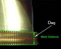
Since R. Gierlinger’s new high precision set has sizes and curvature radii that are different from the stock units, some quantities in the new RA assembly must be meaured, in order to figure out the thickness for the new spacer rings. In particular, three quantities must me measured (“medir distancia”) with a high precision caliper (images courtesy of and (C) by Marco Ferraro):
- The thickness of the worm gear, which we call Dwg:
- After placing the whole EQ6 head on a (horizontal) workbench, the worm gear itself should be slid all the way down the RA shaft with all the bearings, but without the old spacer rings. The fit should be tight enough so as to eliminate any slack, while allowing for a smooth movement if manually rotated. At this point, we are to measure the distance between the DEC housing wall and the worm gear’s upper rim, which we call Hwg:
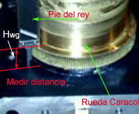
- Last but not least, we have to measure the distance between the worm housing side and the worm shaft center (let it be Hs), and finally the diameter of the worm shaft itself (Dw in the figure below):
The thickness for the new spacer ring Tsr can be found by feeding the actual values into the following expression:
Tsr = Hs – [Hwg – (Dwg / 2)] – Dw / 2
The following table shows all sizes (in mm) and the result of the above formula for three different mounts: Marco Ferraro’s, the one tested by the deepsky.de staff, and of course mine:
| Quantity | Marco Ferraro | Deepsky.de | My EQ6 |
| Dwg | 12.06 | 12.02 | 11.45 |
| Hwg | 19.62 | 19.21 | 19.60 |
| Hs | 17.93 | 17.91 | 17.70 |
| Dw | 8.00 | 8.00 | 8.00 |
| Tsr | 0.34 | 0.70 | -0.18 |
As can be seen from the above data, Marco Ferraro had to make a new spacer ring 0.34 mm thick, while the folks at deepsky.de fixed their mount mesh by adding an extra 0.2-mm build-up to the 0.5-mm stock spacer ring. But what’s the matter with my unit?-0.18 is a negative value: how on Earth could I rig up such a spacer ring?
As surprising as it may sound, the answer to this question is quite simple: a negative-valued spacer ring thickness actually means that the worm gear is too distant from the dec housing surface; therefore, a layer of about 0.15-0.20 mm has to be lathed off the inner side of the worm gear, which is what I actually did together with a friend of mine. And, needless to say, no spacer ring whatsoever is needed!
After the fine tuning the mesh, we turned our attention to another critical adjustment: RA shaft orthogonality with respect to the DEC housing surface, so as to ensure the smoothest rotation for the worm gear. For precise details on how to perform this mod, please refer either to this page (in Spanish, again by Marco Ferraro), or to this article in German by the deepsky.de team. We used a 0.01-mm dial gauge with magnetic stand such as this one:

but since the mount head is made of aluminium, and doesn’t give a damn about magnetic field :-), we managed to firmly attach the stand base to the DEC housing surface with a patch of strong double-sided adhesive tape. Subsequently, we gently rotated the worm gear about the RA shaft while watching the dial gauge. Fortunately, the worm gear rotation turned out to be very smooth (less than 0.05 mm as measured ~ 10 cm above the DEC housing surface), so we decided not to carry our investigation any further.
This time, we put back together the RA axis with a pretty snug fit, but not tight enough to cause any binding: my motor drive was free to complete quite a few GoTo cycles with a decent payload (C9.25 SCT plus accessories and counterweights) without any significant glitch.
Update #2 (April 2006): PE measurement after RA mesh adjustment
Now, let’s check if (and how) the latest modifications affected the PE of my mount. On 22nd April, 2006, during an observing session, I managed to get two PE measurements with different stars and telescope orientations. The first one was performed on Arcturus, while the second on Vega; both were corrected for declination of the target star. Furthermore, I used my my trusty Philips ToUcam Pro webcam and K3CCD Tools 1 for acquisition and data logging.
Here are the plots and FFT analysis:
Conclusion (so far, i.e. early May 2006)
Though some improvement has been achieved, work is still in progress. In april 2006, Mr. Gierlinger kindly sent me a new worm, which I’ll replace as soon as I can. Check this page back often, as there is more to come!
Resources
Here are a few resources/links that might come in handy:
- EQ6 Yahoo user group THE reference group for all EQ6 mount owners. .
- EQ6-Italia user group: italian EQ6 mount user group.
- Skywatcher telescopes official website.
- Want to take your mount apart? Then check out James Robert cook’s wonderful article: EQ6 Dismantle Guide.
- Still want to take your mount apart but want something in Italian? Then this article by Marco Fazzoli could be of some help.
- Gierlinger gear set replacement and spacer ring calibration procedure: article from deepsky.de (in German). Other EQ6-related articles from deepsky.de can be found at this link.
- Marco Ferraro’s website probably features the best and clearest explanation on how to dismantle an EQ6, install Gierlinger’s high-precision set and calibrate the spacer rings. Definitely a must-see! (In Spanish).